
Modernizing Airport FIDS Displays: Direct-View LED Video Walls, Engineering & Deployment
Airport FIDS modernization is not simply a screen replacement project. The passenger-facing display is the final layer of a larger information chain that can include an Airport Operational Database, other operational data sources, FIDS software, middleware, rendering systems, display controllers, network infrastructure, and the physical display itself.
Direct-view LED, or dvLED, can be a strong alternative to tiled LCD video walls when an airport needs a large continuous canvas, custom dimensions, bezel-free information layouts, or modular serviceability. It is not automatically the best choice for every flight information screen. Commercial LCDs may better serve smaller gate, check-in, baggage, and distributed FIDS endpoints.
A successful modernization program should therefore answer three questions:
- Is DVLED the right display technology for this particular location?
- How will the new display operate within the airport’s existing FIDS and flight-data environment?
- How will the display be surveyed, installed, commissioned, maintained, and supported throughout its lifecycle?
What Is Airport FIDS Display Modernization?
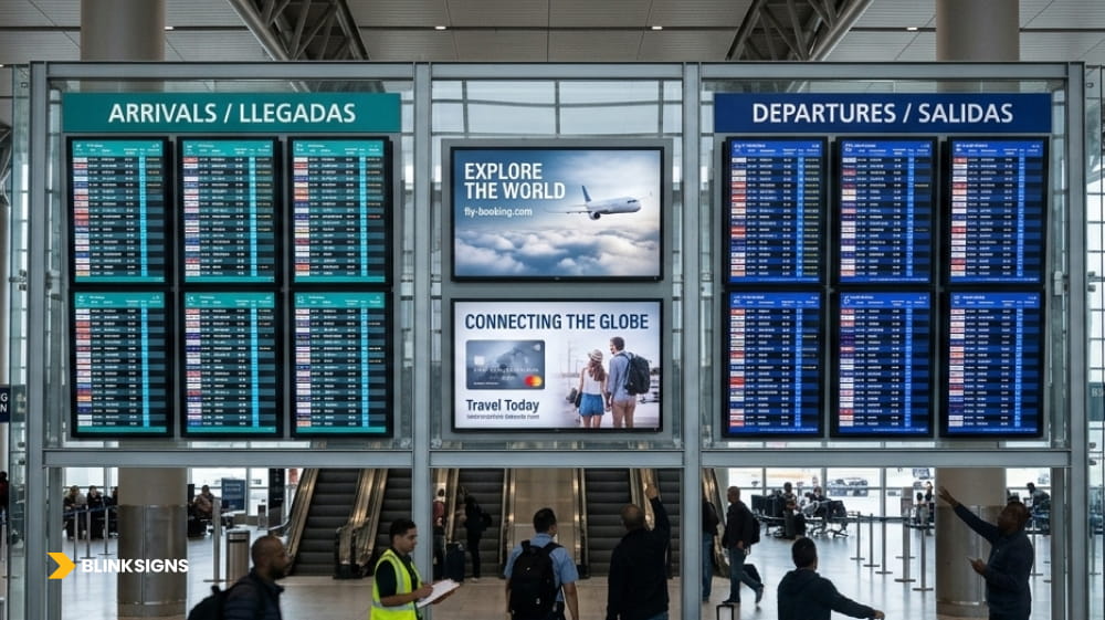
Integrated terminal arrivals and departures network.
Airport FIDS display modernization upgrades the physical infrastructure that presents live flight information while preserving the reliable operation of the airport’s existing flight data and FIDS environment. Depending on the project, modernization can include new displays, mounting systems, display controllers, power, installation, commissioning, maintenance planning, and coordination with airport IT and specialist FIDS providers.
A Flight Information Display System is more than the screen passengers see.
The passenger-facing layer may show:
- arrivals and departures;
- flight numbers;
- airline names;
- gates;
- boarding status;
- delays;
- cancellations;
- baggage information;
- codeshares;
- wayfinding or service information.
Behind those displays, flight information normally originates from airport and airline operational systems before being processed for presentation.
The Airport Cooperative Research Program describes the Airport Operational Database (AODB) as a central repository of airport information used by operational systems. Its role can include supplying flight-related information to systems such as FIDS.
IATA’s Aviation Information Data Exchange Model, or AIDM, similarly reflects the aviation industry’s need for consistent data definitions so information can move reliably between different systems.
The practical implication is important:
Replacing an LCD wall with dvLED can modernize the visualization layer without replacing the airport’s AODB or underlying FIDS platform.
What Is the Difference Between FIDS and MUFIDS?
FIDS refers broadly to systems that present flight information to passengers and airport users. MUFIDS, or Multi-User Flight Information Display System, is commonly used in shared environments where multiple airlines or operational stakeholders use a common passenger information infrastructure.
Terminology can vary between airports and technology vendors.
For procurement and integration planning, the important step is not simply deciding whether the system should be called FIDS or MUFIDS. The project team should clearly define:
- where authoritative flight data originates;
- which application controls passenger information;
- which systems render the screen layouts;
- Which team owns the display hardware;
- which interfaces are staying in place;
- which components are actually being replaced.
This prevents a display modernization project from unintentionally expanding into an undefined airport-software replacement.
Why Are Airports Replacing Some LCD FIDS Walls With Direct-View LED?
Direct-view LED becomes particularly attractive when an airport needs a large continuous FIDS canvas, custom dimensions, bezel-free layouts, or modular serviceability. The strongest use cases are generally large departure, arrival, and passenger information walls rather than every individual display endpoint.
Traditional LCD video walls combine several commercial panels into one visual surface.
That architecture can work well, but each panel has a physical border. Even narrow-bezel displays create visible lines across the information canvas.
Those seams can interrupt:
- flight-information rows;
- text;
- tables;
- airline branding;
- maps;
- graphics;
- advertising;
- passenger messaging.
dvLED uses modular cabinets or LED modules instead of multiple self-contained LCD screens. This allows a continuous display surface without conventional panel bezels.
Real airport deployments demonstrate the use case.
Brussels Airport replaced aging 46-inch narrow-bezel LCD FIDS video walls with fine-pitch 1.2 mm LED after approximately seven years of LCD operation, according to Sharp’s published project case study.
Cologne Bonn Airport also deployed 1.2 mm dvLED displays for FIDS applications. According to Sharp’s case study, the project considered display size, location, high-resolution data requirements, structural integration, serviceability, and fire protection.
These projects demonstrate that dvLED can be an appropriate FIDS technology.
They do not establish that DVLED is the best choice for every airport display.
When Is LCD Still the Better Choice for Airport FIDS?
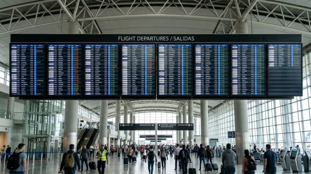
High-density LCD arrays for terminal concourses.
LCD remains practical when a single commercial display, or a small number of displays, can provide the required dimensions, resolution, brightness, service model, and readability without the need for a large, seamless canvas.
LCD can remain a strong choice for:
- departure-gate displays;
- check-in positions;
- baggage-information screens;
- staff-facing displays;
- small arrival or departure displays;
- distributed passenger-information endpoints.
Replacing every airport LCD with dvLED simply because LED technology is newer can increase complexity without generating enough additional operational value.
LCD may remain the better choice when:
- One panel already provides sufficient display area;
- native panel resolution comfortably supports the required text;
- A bezel-free canvas provides little operational benefit;
- Custom dimensions are unnecessary;
- panel replacement is straightforward;
- The existing mounting and infrastructure remain suitable.
The correct question is therefore not:
Which technology is newer?
It is:
Which display architecture best serves the information, viewing, maintenance, physical, and lifecycle requirements of this location?
dvLED vs. LCD for Airport FIDS
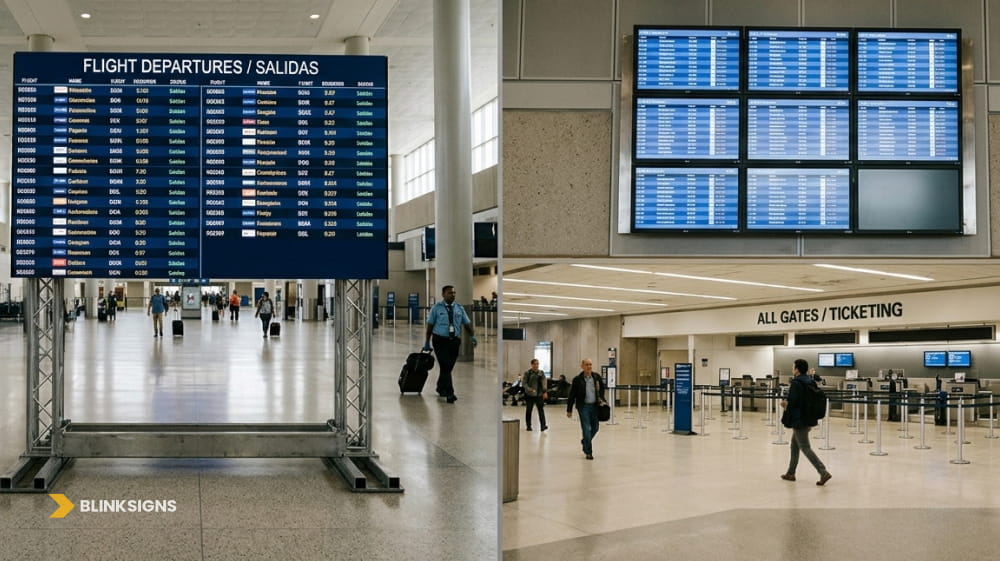
Comparing dvLED and LCD flight boards.
The key difference between dvLED and LCD is not simply picture quality. It is how each architecture behaves when an airport needs to create and maintain a large operational passenger-information surface.
| Evaluation Area | Direct-View LED | Commercial LCD |
| Visual seams | Continuous bezel-free canvas is possible | Panel bezels remain visible |
| Display dimensions | Highly configurable | Based on available panel sizes |
| Large FIDS walls | Strong fit | Requires tiled panels |
| Small distributed displays | Often unnecessary | Frequently practical |
| Resolution | Determined by pixel pitch and wall dimensions | Determined mainly by the native panel resolution |
| Dense FIDS text | Requires sufficient total pixel resolution | High native resolution can be advantageous |
| Service model | Modules/components may be individually serviced | Individual panels are typically replaced |
| Custom aspect ratios | Highly flexible | More constrained |
| Installation complexity | Requires precise LED alignment and supporting infrastructure | Usually simpler for individual screens |
| Best-fit use case | Large arrival/departure and information walls | Gates, counters, baggage areas, and smaller endpoints |
For dense FIDS content, dvLED should not be selected merely because it creates a seamless wall. The selected pixel pitch and total display dimensions must still provide sufficient usable resolution for the smallest required characters and the required number of information rows.
How Does Flight Data Reach an Airport FIDS Display?
An airport display normally does not consume raw AODB data directly. Operational flight information is typically processed by a FIDS application or integration layer, formatted for passengers, rendered into a visual layout, and then delivered through the display-control system to the LCD or dvLED surface.
A simplified reference architecture is:
AODB / authoritative operational sources
 ↓
 FIDS application or integration layer
 ↓
 template and rendering system
 ↓
 media server / display-control layer
 ↓
 dvLED processor or LCD endpoint
 ↓
 passenger-facing FIDS display
This is a reference architecture, not a mandatory airport-industry topology.
Actual systems can combine or separate these functions in different ways.
Some FIDS platforms include rendering and device management within the application itself. Other environments may use separate middleware, APIs, media servers, AV control systems, digital-signage platforms, or proprietary airport interfaces.
The critical distinction is that:
The physical display is normally the endpoint of the information chain, not the airport operational database itself.
Therefore, changing the display does not automatically require changing the AODB.
Does Airport FIDS Require XML or JSON Socket Integration?
No. Every airport uses a non-universal AODB-to-FIDS communication method. XML and JSON are possible data formats, but real systems may also use APIs, middleware, aviation messaging, vendor-specific connectors, database interfaces, or proprietary integration methods.
For example, PDC documents AODB capabilities for exchanging information using XML and JSON, as well as aviation messaging.
Cirium’s FIDS API is another example of an interface that can expose information through XML or JSON.
These are examples of real integration approaches.
They are not universal standards for all airports.
The stronger engineering question is:
What interface does the airport’s existing FIDS environment require, and which technology team owns that interface?
That answer should come from the airport’s IT architecture, FIDS provider, AODB provider, and systems-integration teams.
Who Owns Each Part of a FIDS Modernization Project?
Airport FIDS modernization normally crosses several technical and physical disciplines. Responsibility should be defined before procurement so that software, data, AV, display, installation, and maintenance responsibilities do not fall through the cracks between suppliers.
A typical responsibility model may look like this:
Airport IT and operations
Own operational requirements, network architecture, security policy, system access, and internal technology governance.
AODB provider
Owns the operational database platform and supports data interfaces within its contracted scope.
FIDS provider
Owns the passenger-information application, business rules, templates, and application-level integrations within its scope.
Systems or AV integrator
May own rendering, signal routing, control architecture, middleware, or display-controller integration.
Display manufacturer
Owns the DVLED or LCD hardware, product-specific processing equipment, manufacturer specifications, and product warranties.
Physical deployment partner
Handles relevant site conditions, mounting, signage/display infrastructure, physical installation, field coordination, and display-side QA within contracted scope.
Maintenance teams
Own ongoing service according to the final support model.
The exact allocation varies by airport.
What matters is making the boundaries explicit.
How Should Airports Choose Pixel Pitch for an FIDS LED Wall?
There is no universal pixel pitch for airport FIDS. Pixel pitch should be selected only after the required character legibility, viewing distances, wall dimensions, information density, and target canvas resolution have been determined.
Airport FIDS can be especially demanding because the content often includes:
- small characters;
- flight numbers;
- departure and arrival times;
- airport codes;
- airline names;
- gates;
- status messages;
- dense rows of structured information.
A display that looks excellent when showing video may still perform poorly when rendering dense FIDS text.
A better design process starts with the content.
Start with what passengers must read.
The project team should determine:
- the smallest important character;
- the nearest expected viewing position;
- the farthest useful viewing position;
- the number of flight rows required;
- the physical dimensions of the proposed wall;
- The pixel resolution needed to render the layout cleanly.
Only after those requirements are understood should an appropriate LED pixel pitch be selected.
Cologne Bonn Airport’s 1.2 mm installation demonstrates how a fine pixel pitch can be selected to meet a specific high-resolution FIDS requirement.
It does not mean P1.2 is a universal airport standard.
How Bright Should an Airport FIDS Display Be?
There is no single brightness level that should be applied to every airport’s FIDS. Brightness should be specified against the actual terminal environment, including ambient illumination, daylight exposure, glare, display orientation, viewing angles, contrast, and operating conditions.
The following are project-planning factors rather than universal standards for airport brightness.
A display facing extensive exterior glazing may experience very different lighting conditions from an FIDS located deep inside a controlled concourse.
The site assessment should therefore consider:
- direct daylight;
- indirect daylight;
- terminal lighting;
- reflections;
- glare;
- viewing angle;
- display orientation;
- content background;
- required text contrast;
- operating schedule.
The best brightness specification is the one that ensures reliable readability in the actual installation environment, rather than treating maximum panel output as the operating target.
Why Do Service Access and Module Replacement Matter?
Airport FIDS is an operationally important passenger information infrastructure, so maintainability should be planned before the display is installed. An LED wall should allow technicians to access relevant modules, power components, receiving hardware, controllers, and supporting systems without causing unnecessary disruption to the terminal.
One potential advantage of modular dvLED is that a failure does not always require replacing the entire display.
Depending on the selected system, serviceable components can include:
- LED modules;
- power supplies;
- receiving cards;
- cabinets;
- controllers;
- signal components.
That benefit depends heavily on physical design.
A wall installed against a solid architectural surface may require front-serviceable LED modules. Another installation may provide sufficient rear access.
Important planning questions include:
- Can a failed module be removed without dismantling neighboring areas?
- Can technicians safely reach the display?
- Where will critical spare components be stored?
- Are controllers accessible after the architectural finishes are complete?
- Can service occur without unnecessarily disrupting passengers?
According to Sharp’s Cologne Bonn case study, serviceability influenced the design, including the ability to replace affected cabinets without replacing the complete installation.
How Should Redundancy Be Planned for Airport FIDS?
FIDS resilience should be considered across the entire source-to-screen chain. Display-controller backup alone cannot protect passengers from stale operational data, a failed FIDS application, a broken network path, or an upstream rendering failure.
A layered review should consider:
Operational source
What happens if the authoritative flight-data source becomes unavailable?
FIDS application
Can another service or node continue the passenger-information function?
Rendering layer
What happens if the primary rendering system fails?
Network
Are critical paths designed in accordance with the airport’s resilience requirements?
Display controller
Does the selected LED control architecture provide appropriate backup?
Signal path
Can a failed fiber or Ethernet path be bypassed where required?
Display hardware
Can component failures be isolated without losing the complete canvas?
NovaStar’s COEX documentation provides one vendor-specific example of hot-backup capabilities. Supported configurations can provide backup at the controller, fiber, Ethernet, or output-card layers, depending on the selected hardware and topology.
That is an example of available display-layer technology, not a universal airport redundancy specification.
What Happens if FIDS Data Becomes Stale?
A FIDS screen that remains illuminated while showing outdated flight information can be more misleading than a clearly failed display. Airport teams should therefore monitor the freshness of information and the physical condition of displays.
This article recommends separating two concepts:
Display health
Is the screen powered, receiving a signal, and physically functioning?
Information health
Is the displayed flight information current and consistent with the authoritative source?
The exact stale-data thresholds should be defined by the airport and its FIDS technology provider. There is no universal timeout recommended here.
As a practical operational-control principle, the system should be able to:
- identify missing or outdated data;
- alert the responsible operational team;
- distinguish data failure from display failure;
- Execute a predetermined fallback process where appropriate.
This matters because passengers cannot determine from appearance alone whether a normal-looking gate assignment or departure time has stopped updating.
What Should an Airport FIDS Site Survey Evaluate?
Evaluating sites for large flight displays.
A FIDS site survey should document the physical conditions that determine whether the display can be installed, seen, powered, serviced, and maintained effectively. The survey should take place before the final display dimensions and installation assumptions are locked in.
Relevant physical conditions can include:
- available wall dimensions;
- supporting structure;
- mounting conditions;
- nearest and farthest viewing distances;
- passenger sightlines;
- ambient light;
- daylight exposure;
- service access;
- equipment access routes;
- available power;
- network handoff location;
- existing displays;
- architectural constraints;
- passenger circulation;
- installation-hour restrictions.
Airports also introduce operational considerations that may not exist in ordinary commercial installations.
Installation teams may work around:
- active passenger traffic;
- controlled areas;
- security procedures;
- existing FIDS that must remain operational;
- limited shutdown windows;
- phased cutovers.
BlinkSigns documents site surveys as part of its existing physical-signage services, including measurements, infrastructure assessment, visibility, structural conditions, environmental factors, and installation feasibility.
Airport-specific engineering should still be coordinated with the airport authority, architects, structural and electrical professionals, AV teams, the display manufacturer, the IT organization, and other qualified stakeholders required for the project.
What Fire, Structural, Electrical, and Thermal Requirements Should Be Reviewed?
Airport FIDS display requirements depend on the selected equipment, terminal location, supporting structure, applicable codes, airport standards, electrical design, service strategy, and life-safety requirements. A design used at one airport should not be treated as a universal template.
Large DVLED walls introduce:
- physical load;
- support structures;
- power equipment;
- signal cabling;
- electronic components;
- service requirements;
- heat.
The Cologne Bonn case study illustrates why project-specific engineering matters. According to Sharp, fire safety played an important role in that installation, and the project incorporated low-fire-load LED equipment and a dedicated fire-protection solution.
That is evidence that fire-safety requirements can influence an airport LED project.
It does not mean every airport should use the same fire-suppression design.
Similarly:
Structural requirements should be based on the actual wall, mounting design, equipment weights, and project conditions.
Electrical requirements should be derived from the selected system and operating configuration rather than generic power assumptions.
Thermal requirements should be evaluated against equipment specifications and the terminal environment.
How Should Airport FIDS Be Designed for Readability and Accessibility?
Airport FIDS should be designed around the ability of real passengers to locate and understand essential information. Character size, contrast, glare, viewing distance, sightlines, positioning, information density, and alternative communication methods all matter.
Airport-specific accessibility guidance provides a better starting point than treating FIDS as ordinary static signage.
The Airport Cooperative Research Program’s effective-communication guidance discusses FIDS accessibility considerations, including:
- locating displays where passengers can approach them;
- providing appropriate viewing positions;
- high visual contrast;
- managing glare;
- adequate text size;
- accessibility for low-vision passengers;
- accessibility for wheelchair users.
The US Access Board’s ADA guidance also provides useful principles for applicable visual signs, including contrast, non-glare finishes, character properties, and viewing relationships.
However, the article should not claim that selecting a particular dvLED product automatically produces an “ADA-compliant FIDS.”
Airport passenger communication can involve dynamic displays, announcements, airport operations, airline responsibilities, and other accessible communication channels.
The broader objective is:
Passengers should be able to obtain important trip information accurately through accessible communication methods appropriate to the airport environment.
Recommended Source-to-Screen FIDS Commissioning Framework
FIDS commissioning should verify that a real operational event travels correctly from the authoritative source to the passenger-facing display. Testing only whether the LED wall powers on and displays a test image is not enough.
The following is a recommended planning framework, not an airport-industry standard.
Step 1: Create or simulate an operational event
Examples can include:
- gate change;
- delay;
- boarding-status change;
- cancellation;
- baggage change.
Step 2: Verify the authoritative data source
Confirm that the correct event exists in the source system.
Step 3: Verify FIDS processing
Confirm that the FIDS receives and interprets the event correctly.
Step 4: Verify rendering
Confirm that the event appears in the correct passenger information template.
Step 5: Verify display control
Confirm that the rendering system delivers the correct output to the display environment.
Step 6: Verify the passenger-facing result
Confirm that the correct information appears on the correct screen or wall and remains readable under normal operating conditions.
Failure Testing
Commissioning should also test agreed failure scenarios within the scope of the responsible project teams.
Examples can include:
- upstream data interruption;
- FIDS service failure;
- rendering-node failure;
- network interruption;
- display-controller failover;
- LED module failure;
- power interruption;
- power restoration.
Airport IT, the FIDS provider, the AODB provider, the AV integrator, the display manufacturer, and the physical installation teams should participate in accordance with their respective responsibilities.
Test Recovery Synchronization
After a failure is restored, the display should be verified against the current authoritative flight state rather than merely returning to the last information stored before the outage.
For example:
Before an outage, a flight is assigned to Gate A12.
During the outage, operations changed the flight to Gate A18.
When the affected service returns, commissioning should verify that the FIDS reconciles to the current authoritative A18 assignment rather than restoring an outdated cached A12 display.
This recovery test helps distinguish simple system availability from information integrity.
BlinkSigns’ existing installation capabilities include physical installation, alignment, quality assurance, and post-installation support within its documented signage scope.
What Determines the Lifecycle Cost of an Airport FIDS Display?
The lifecycle cost of an airport FIDS wall includes much more than the purchase price of the LED or LCD hardware. Airports should evaluate the complete cost of installation, controllers, supporting infrastructure, service access, maintenance, spare parts, labor, power, support, component availability, and eventual replacement.
Useful lifecycle questions include:
- How are failed modules replaced?
- What spare components should be retained?
- How long are critical components expected to remain supported?
- What is the controller migration path if hardware becomes obsolete?
- Who diagnoses failures?
- Who owns software and firmware support?
- What does the warranty actually include?
- Is special access equipment needed for maintenance?
- Can the display be serviced without prolonged disruption to the terminal?
- What happens when a component reaches end-of-life?
Brussels Airport provides a useful lifecycle example because its previous LCD FIDS walls had operated for approximately seven years before the airport transitioned those locations to dvLED.
That is a project history, not a recommended seven-year replacement interval.
For a broader breakdown of display hardware, mounting, installation, CMS, power, network readiness, maintenance, support, and replacement considerations, see the BlinkSigns Digital Signage Cost Guide.
How Should Airports Plan Multi-Terminal FIDS Modernization?
A multi-terminal FIDS program should be managed as a phased infrastructure deployment rather than as a series of unrelated screen replacements. Standardization, exception management, installation sequencing, QA, and centralized project visibility become increasingly important as the number of locations grows.
A useful planning sequence is:
audit existing conditions → define standards → pilot representative locations → document exceptions → deploy in controlled waves → stabilize → transfer to operations
This is a recommended planning framework, not an industry standard, for airports.
For each location, the program should establish:
- existing display type;
- physical dimensions;
- target display architecture;
- viewing requirements;
- structural conditions;
- power and network handoffs;
- responsible technology teams;
- installation windows;
- commissioning requirements;
- temporary passenger information arrangements;
- maintenance ownership.
The objective is to standardize what is standardizable while allowing controlled exceptions where terminal conditions differ.
BlinkSigns already applies a similar infrastructure-first approach to enterprise display programs in its Large-Scale Digital Signage Deployment Framework.
Where Does BlinkSigns Fit in Airport FIDS Modernization?
BlinkSigns’ most defensible role is at the physical display and deployment layer. Depending on project scope, that can include site surveys, display and signage planning, fabrication where applicable, physical installation coordination, quality assurance, maintenance planning, field support, and multi-location project visibility.
BlinkSigns should not be positioned as an AODB software provider or FIDS application developer simply because the physical display shows airport operational data.
A clear project boundary looks like this:
Airport IT and FIDS specialists
Responsible for areas such as:
- AODB;
- FIDS applications;
- APIs;
- middleware;
- operational-data validation;
- airport network architecture;
- cybersecurity;
- software failover.
AV/control and display specialists
May be responsible for:
- rendering;
- signal distribution;
- display processing;
- LED controller configuration;
- manufacturer-specific display integration.
BlinkSigns and physical deployment teams
Can support a relevant physical scope, such as:
- site surveys;
- display planning;
- signage/display infrastructure;
- installation coordination;
- QA;
- project visibility;
- field support;
- Maintenance where applicable.
BlinkSigns services publicly documents digital displays, site surveys, installation and quality assurance, repair and maintenance assessment, SignTrax project tracking, and a nationwide installer network.
Clear responsibility boundaries help the airport understand exactly which supplier owns each layer before the project reaches commissioning.
What Should Be Included in an Airport FIDS Modernization RFP?
A strong FIDS modernization RFP should define the existing environment, desired passenger-information outcome, display requirements, responsibility boundaries, physical site conditions, maintenance expectations, data ownership, commissioning criteria, and lifecycle support before vendors submit final solutions.
The RFP should address the following areas.
Existing System
Document:
- current FIDS platform;
- current AODB or operational sources;
- existing display architecture;
- rendering/control systems;
- network dependencies;
- systems that will remain in place.
Responsibility Boundaries
Define who owns:
- AODB integration;
- FIDS application;
- APIs;
- middleware;
- network architecture;
- rendering;
- LED processing;
- physical installation;
- commissioning;
- maintenance.
Data and Interface Ownership
Confirm:
- who owns API credentials;
- who maintains interface documentation;
- who maintains field mappings;
- Who pays for middleware licenses;
- who supports the integration after go-live;
- Who owns escalation when an interface stops updating?
Display Requirements
Define:
- display purpose;
- wall dimensions;
- smallest required information;
- number of flight rows;
- nearest and farthest viewing distances;
- operating hours;
- whether a seamless canvas is necessary.
Site Conditions
Document:
- structure;
- mounting;
- ambient light;
- power;
- network handoff;
- equipment access;
- service clearance;
- terminal operating restrictions.
Maintainability
Require vendors to explain:
- front or rear service model;
- module replacement;
- controller access;
- spare-parts strategy;
- warranty;
- response model;
- field-support responsibility.
Resilience
Define the required behavior for relevant:
- data-source failure;
- application failure;
- rendering failure;
- network failure;
- controller failure;
- power loss;
- display-component failure.
Information Integrity
Define:
- stale-data monitoring;
- operational alerts;
- fallback behavior;
- recovery synchronization.
Accessibility and Readability
Require project review of:
- character legibility;
- viewing distance;
- contrast;
- glare;
- sightlines;
- information hierarchy;
- applicable accessibility obligations.
Commissioning
Require source-to-screen testing using real or simulated flight events, along with agreed failure and recovery scenarios.
Documentation
Require appropriate:
- as-built documentation;
- equipment schedules;
- controller records;
- configuration records;
- warranties;
- spare parts documentation;
- support contacts;
- operating procedures.
End-of-Life and Obsolescence
Ask suppliers to document:
- expected support period;
- module availability;
- controller migration path;
- critical spare-parts strategy;
- software dependencies;
- expected replacement planning.
A well-defined RFP does not require one vendor to own the entire FIDS ecosystem.
It ensures that every important responsibility has an owner.
Frequently Asked Questions About Airport FIDS Modernization
Can Direct-View LED Replace an LCD FIDS Video Wall?
Yes. dvLED can replace a tiled LCD wall when the project benefits from a large continuous canvas, custom dimensions, bezel-free layouts, or modular serviceability. It should not automatically replace every smaller airport display.
Brussels Airport and Cologne Bonn Airport provide documented examples of major FIDS locations using fine-pitch LED.
Does an LED FIDS Wall Connect Directly to the AODB?
Usually not. Operational data normally passes through a FIDS application or integration layer before it is rendered for the passenger-facing display.
The exact architecture depends on the airport and its technology providers.
What Pixel Pitch Is Best for Airport FIDS?
There is no universal best pixel pitch.
Selection should be based on:
- viewing distance;
- smallest required text;
- information density;
- wall dimensions;
- required canvas resolution.
A pitch that was successful at one airport should not automatically become another airport’s specification.
Is DVLED Better Than LCD for Every Airport Display?
No.
DVLED is particularly attractive for large continuous display surfaces, while LCD remains practical for many gates, counters, baggage areas, and smaller distributed information displays.
How Is FIDS Redundancy Designed?
Resilience should be reviewed across the operational data, software, rendering, network, controller, signal, power, and physical display layers.
The correct architecture depends on the airport’s requirements and the selected technology stack.
What Happens if FIDS Data Stops Updating?
The airport should be able to distinguish between a failed display and one that is still operating but displaying outdated information.
The airport and FIDS provider should define stale-data detection, alerting, fallback behavior, and recovery rules appropriate to the system.
What Should Be Tested During FIDS Commissioning?
Commissioning should verify the complete source-to-screen chain.
A real or simulated flight event should be traced from the authoritative source through the FIDS and rendering environment until the correct passenger information appears on the intended screen.
Fault and recovery behavior should also be tested in accordance with the project scope.
Who Handles AODB Integration During a BlinkSigns FIDS Project?
AODB and FIDS software integration should remain within the airport’s IT organization and with qualified airport technology or systems-integration providers unless a specialist partner has been explicitly engaged for that work.
BlinkSigns’ strongest fit is in the physical display, site assessment, installation, project management, and maintenance layers within its documented capabilities.
Modernize the Display Without Losing Sight of the System
The best airport FIDS modernization projects improve the passenger-facing display while preserving the integrity of the complete information chain behind it.
The AODB or another operational source determines the origin of flight information.
The FIDS application determines how that information is processed for passengers.
The integration and rendering systems determine how the information becomes visual content.
The display-control system delivers that content to the screen.
The physical display determines whether passengers can see and understand it.
The installation determines whether the system can be serviced.
The commissioning process determines whether the source-to-screen chain actually works.
And the responsibility model determines who fixes it when something fails.
Direct-view LED can be an excellent choice when an airport needs a large, seamless, serviceable passenger-information canvas.
LCD can remain the better choice for smaller distributed endpoints.
The objective should therefore not be:
Replace every LCD with an LED.
It should be:
Build a reliable, readable, and maintainable FIDS display environment in which the display technology, information architecture, physical installation, and lifecycle plan all align with the airport’s operational requirements.
For airport teams evaluating the physical modernization of FIDS or other large digital display environments, BlinkSigns can support site surveys, display planning, installation, quality assurance, project management, and maintenance requirements, while coordinating the physical display scope with the airport’s existing FIDS, AODB, AV, and IT partners.